The client operated two related companies from the same physical location. They shared ownership and infrastructure, but they remained separate entities. One company could eventually be relocated, sold, or separated operationally.
That business condition changed the meaning of redundancy. The network had to behave as one resilient environment during normal operation while avoiding dependencies that would make a future separation expensive or disruptive.
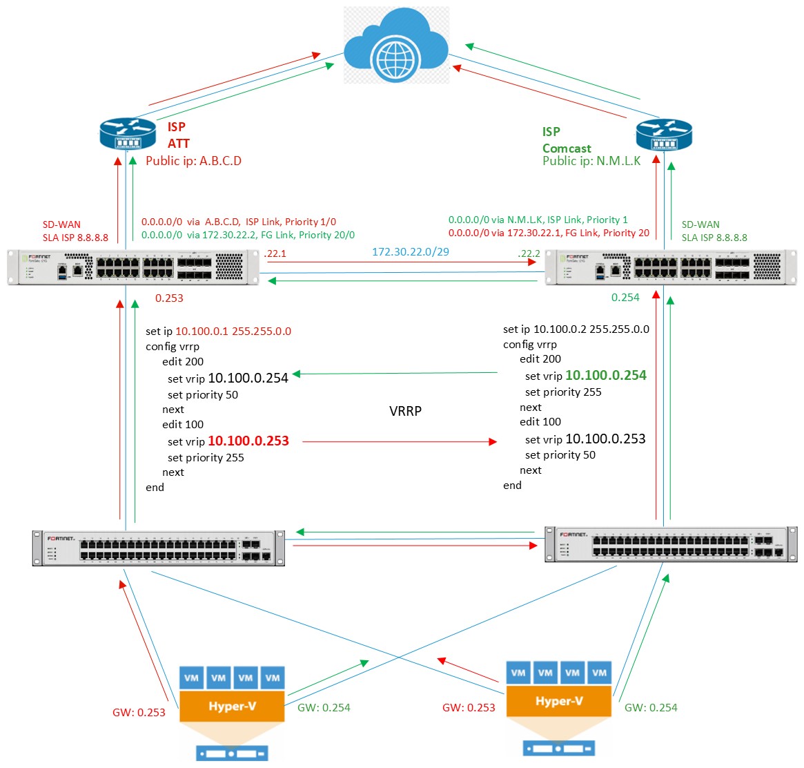
The resulting design uses two FortiGate 121G firewalls as independent active systems rather than members of one cluster. Crossed VRRP roles, dual ISPs, SD-WAN monitoring, aggregated links, redundant switching, and Hyper-V NIC Teaming provide availability at several layers. The tradeoff is equally important: there is no automatic policy, state, or configuration synchronization between the firewalls.
The addresses and selected names below are simplified and fictitious. They describe the architecture without exposing the client’s production configuration.
Why Not an FGCP HA Cluster?
FGCP HA is the conventional choice when two compatible FortiGates should behave as one managed firewall pair. It provides capabilities that this design intentionally does not reproduce, including configuration synchronization and session-state coordination.
But a cluster also creates a strong operational bond between its members. Here, the two sides needed to remain independently manageable because each one could eventually become the complete network edge for a separate company.
The requirement was not simply “survive a firewall failure.” It was “share a resilient infrastructure without eliminating the ability to separate it later.”
The architecture therefore favors symmetry over clustering. Each side has its own firewall, ISP, switching path, addressing responsibilities, and configuration. During normal operation both sides carry traffic. During a failure, the surviving side assumes additional gateway or Internet-routing responsibility.
Architecture at a Glance
The solution combines:
- Two independent FortiGate 121G firewalls.
- Two independent Internet service providers.
- Two FortiSwitches for the virtualization environment.
- Two access switches for physical computers and devices.
- Two dedicated VoIP switches.
- Physical Hyper-V servers with dual network adapters.
- A direct aggregated transit link between the FortiGates.
- Crossed VRRP gateway roles.
- SD-WAN monitoring of each local ISP.
- 802.3ad link aggregation and host NIC Teaming.
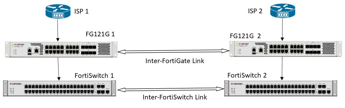
The two sides are architecturally symmetrical, but symmetry does not require identical policies or published services. Each company can retain different responsibilities while the underlying failover paths remain predictable.
WAN Connectivity and Addressing
FortiGate 1 uses ISP 1 and FortiGate 2 uses ISP 2. Each provider supplies a WAN block and a second public block routed toward the client infrastructure.
The WAN interface is implemented as a Virtual VLAN Switch containing multiple physical ports. FortiOS may represent the construct internally as a hard-switch while the graphical interface presents it as a VLAN Switch. The practical benefit is that multiple ports can participate in the same public segment: one can connect to the provider, another can serve a device that requires a direct public address, and the FortiGate can use another address from the same segment.
FortiGate 1 WAN: 203.0.113.2/29
ISP 1 gateway:   203.0.113.1

FortiGate 2 WAN: 198.51.100.2/29
ISP 2 gateway:   198.51.100.1
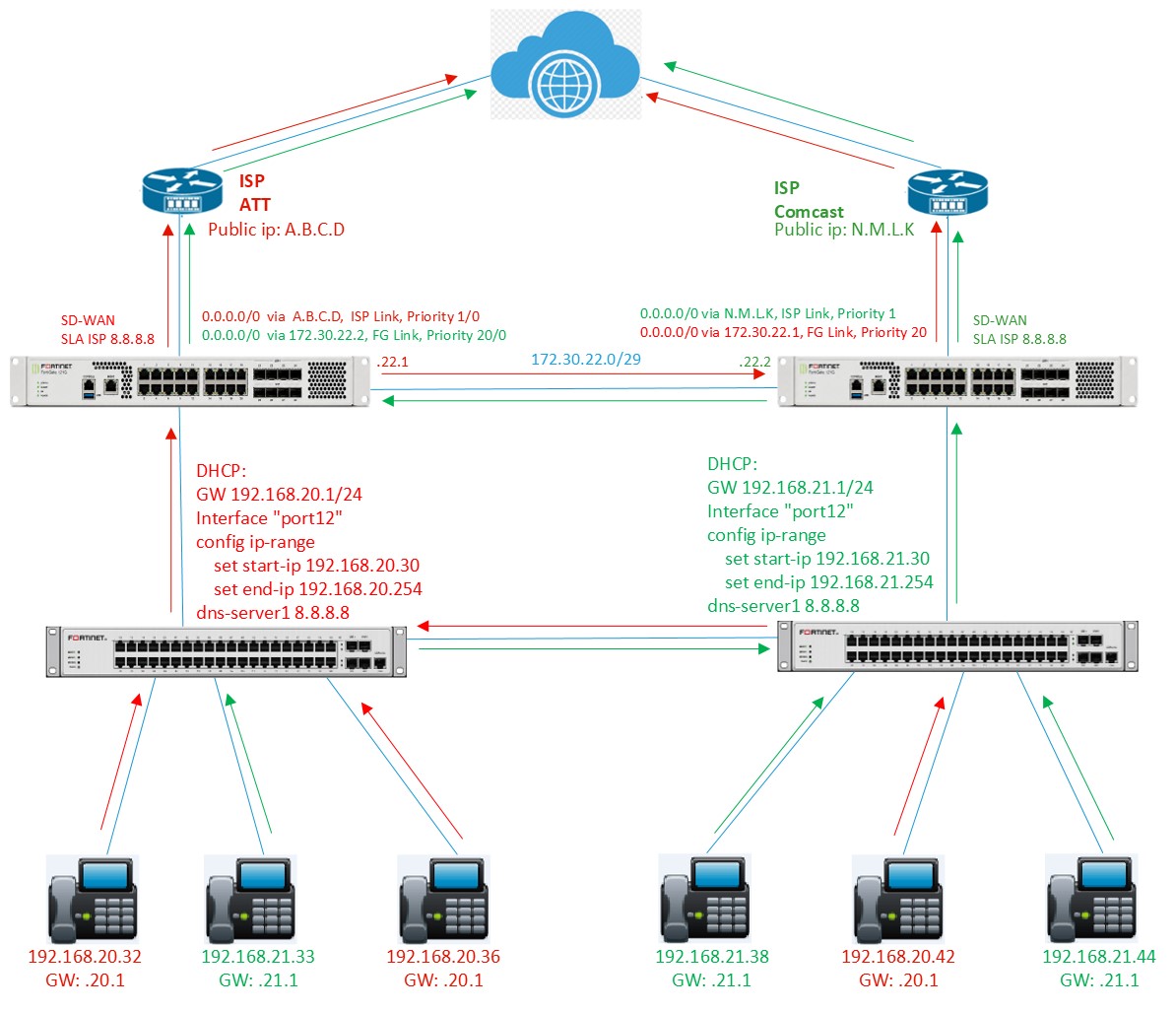
The local ISP remains the preferred path for each firewall. The opposite ISP is reachable through the direct inter-firewall transit link when the local provider is unavailable.
Crossed VRRP Gateways
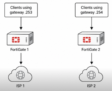
Physical endpoints share the 10.200.0.0/16 network. The firewalls have individual interface addresses, but clients use two VRRP virtual addresses as their default gateways.
FortiGate 1 interface: 10.200.0.1
FortiGate 2 interface: 10.200.0.2

Virtual gateways:
10.200.0.253
10.200.0.254| Virtual gateway | FortiGate 1 | FortiGate 2 |
|---|---|---|
10.200.0.253 | Primary | Backup |
10.200.0.254 | Backup | Primary |
Static client addressing distributes traffic predictably: endpoints with an odd final IP octet use .253; endpoints with an even final octet use .254. This is not dynamic load balancing. It is a simple operational convention that allows both firewalls and both providers to be active while remaining easy to document.
If FortiGate 1 fails, FortiGate 2 stops receiving its VRRP advertisements and assumes .253 in addition to .254. The opposite occurs when FortiGate 2 fails. Clients retain the same addresses and gateways.
VoIP Redundancy with Dual DHCP
The VoIP environment uses two independent subnets and DHCP services on one interconnected Layer 2 domain.
FortiGate 1 VoIP
Network: 192.168.20.0/24
Gateway: 192.168.20.1
DHCP:    192.168.20.30-254

FortiGate 2 VoIP
Network: 192.168.21.0/24
Gateway: 192.168.21.1
DHCP:    192.168.21.30-254
When a phone starts, both FortiGates may answer its DHCP request. The endpoint normally accepts the first valid offer and uses the subnet and gateway supplied by that firewall.
This creates service redundancy, but not immediate endpoint failover. A phone that retains a lease from a failed firewall may keep an unreachable gateway until it is restarted or renews its configuration. That recovery boundary must be documented rather than hidden behind the general word “redundant.”
Virtualization and Link Resilience
Each physical Hyper-V host connects one network interface to each FortiSwitch. Windows NIC Teaming presents both adapters as one logical connection, protecting the host from an adapter, cable, switch-port, or complete FortiSwitch failure.

Each FortiGate reaches the virtualization environment through an 802.3ad aggregate named LNK-SW, using members x3 and x4. The virtual environment uses 10.100.0.0/16 with the same crossed-VRRP pattern:
FortiGate 1: 10.100.0.1
FortiGate 2: 10.100.0.2

VRRP gateways:
10.100.0.253
10.100.0.254
Virtual machines follow the same odd/even gateway convention as physical endpoints, so both network stacks remain active during normal operation.
Transit Link and Default Routes
The two firewalls are directly connected through a separate 802.3ad aggregate named LNK-FG, using members x1 and x2.
Transit network: 172.30.22.0/29
FortiGate 1:     172.30.22.1
FortiGate 2:     172.30.22.2
The link supports direct firewall communication and gives each FortiGate a path to the opposite ISP. Each firewall therefore has two default routes:
FortiGate 1
Primary:   0.0.0.0/0 -> ISP 1
Secondary: 0.0.0.0/0 -> FortiGate 2 through LNK-FG

FortiGate 2
Primary:   0.0.0.0/0 -> ISP 2
Secondary: 0.0.0.0/0 -> FortiGate 1 through LNK-FG
Route priorities prefer the local provider. The transit route remains available when monitoring removes the local Internet path.
SD-WAN Monitors Service, Not Just Link State
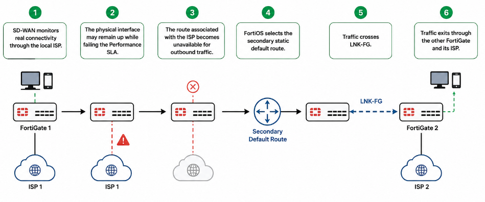
Only the local ISP interface participates in SD-WAN. LNK-FG does not need to be an SD-WAN member because it is the next hop of a secondary static route.
The important distinction is between physical link state and usable Internet service. An ISP-facing interface can remain electrically up while upstream connectivity has failed. The SD-WAN Performance SLA detects that condition and makes the associated route unavailable for outbound traffic.
- SD-WAN monitors real connectivity through the local ISP.
- The interface may remain up while failing the Performance SLA.
- The local ISP route becomes unavailable.
- FortiOS selects the secondary static default route.
- Traffic crosses
LNK-FG. - The opposite FortiGate sends it through the surviving ISP.
Failure Behavior by Scenario
| Failure | Network response | Operational consequence |
|---|---|---|
| One ISP | The affected FortiGate keeps its gateway role and sends outbound traffic across LNK-FG. | Existing transport sessions may need to re-establish through the new stateful path. |
| One FortiGate | The surviving FortiGate assumes both VRRP addresses. | Clients keep their configured gateway; firewall and NAT state are not synchronized. |
| One FortiSwitch | Hyper-V NIC Teaming retains the surviving adapter and switch path. | Capacity and path diversity are reduced until repair. |
| One aggregated-link member | LACP retains the remaining member. | Connectivity remains, with reduced aggregate capacity. |
| One VoIP firewall path | The surviving DHCP service can configure restarted phones. | Phones holding the failed gateway may require restart or lease renewal. |
Application-level session information may remain on the servers, but active TCP, NAT, VPN, and firewall session state should not be treated as synchronized. The recovery expectation must match the layer that actually provides the redundancy.
Seven Layers of Redundancy
- Internet: two independent providers, each monitored by its local FortiGate.
- Firewall: two active FortiGates with crossed VRRP roles.
- Routing: local primary defaults and inter-firewall secondary defaults.
- Switching: paired and interconnected switches for important environments.
- Links: 802.3ad aggregates toward switching and between the firewalls.
- Hosts: dual physical NICs with one connection to each FortiSwitch.
- Resource use: both firewalls, gateways, and ISPs carry normal production traffic.
No single mechanism creates the availability. The design works because gateway ownership, routing, links, switches, and hosts each have a defined failure response.
Design Limitations
This topology provides connectivity redundancy, but it is not equivalent to FGCP HA. The independent FortiGates do not automatically synchronize:
- Firewall policies and address objects.
- NAT tables and active firewall sessions.
- VPN state.
- Configuration changes.
- Connection state.
Configuration drift is therefore an operational risk. Changes must be evaluated on both firewalls, applied symmetrically when required, backed up, documented, and tested. The VoIP design also accepts a manual recovery condition at the endpoint.
These are not minor footnotes. They are the cost of preserving two independent systems. The pattern is defensible only when that independence is a real business requirement and the organization is prepared to operate it.
Operational Diagrams and Implementation
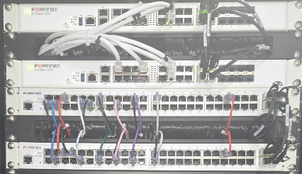
The following views connect the logical design to two concrete operating paths and the physical installation. Select any image to inspect it at full size.
Recommended Operational Controls
- Compare both FortiGate configurations periodically.
- Automate configuration backups and document every change.
- Apply equivalent changes to both sides when the shared design requires them.
- Test the failure of each ISP and each complete FortiGate.
- Test individual LACP members, each FortiSwitch, and Hyper-V NIC Teaming.
- Document the gateway assigned to each physical server and virtual machine.
- Review policies that permit traffic across
LNK-FG. - Monitor VRRP, LACP, SD-WAN SLA status, and physical interfaces.
- Include VoIP restart and lease-recovery procedures in the support runbook.
Regular failover testing is essential because the architecture depends on several coordinated but independent mechanisms. A diagram shows the intended path; only a controlled test proves that routing, policy, state, switching, and endpoint behavior still match it.
Where This Pattern Fits — and Where It Does Not
This pattern is appropriate when two organizations or operating units share infrastructure, both network stacks should be active, future separation is a credible requirement, and the team can maintain two independent firewalls with disciplined change control.
It is a poor fit when the primary requirement is seamless session preservation, one authoritative firewall configuration, minimal operational overhead, or automatic state synchronization. In those conditions, a conventional FortiGate HA design is likely the clearer architecture.
The design should therefore be judged against its operating environment, not presented as a universal alternative to clustering.
Final Principle
Redundancy is not the number of devices in a rack. It is the collection of explicit failure behaviors across gateways, routes, links, switches, hosts, services, and operations.
This architecture succeeds when two independent sides can work together without losing the ability to stand alone.